Reinforced Concrete
Reinforced concrete is the most commonly used of all building materials in structural engineering in the UK, ahead of steel, wood, stone, brick, and masonry.
It’s also the world’s most used material, after water.
In 2020…
14.0 billion cubic meters of concrete were produced globally.
Of which…
40 per cent was used in residential structural building. (Source: Global Cement and Concrete Association).
Typical Uses of Concrete Construction
Studies
Reinforced concrete is most often used in civil engineering for a range of private residential buildings, public and commercial property, and transport infrastructure. Typical uses range from corporate skyscrapers to nuclear reactors and hydro-energy dams. Transport networks, such as rail and road bridges, highways and roads, to paving stones, kerbs, pipelines, and drains.
Statistics
The use of reinforced concrete for residential dwellings is not only the number one material in the world but also continues to grow. Half (55 per cent) of the world’s population lives in urban areas. Over two thirds (68 per cent) of the world’s population is projected to live in urban areas by 2050. Source: UN Department of Economic and Social Affairs – UN DESA, 2018)
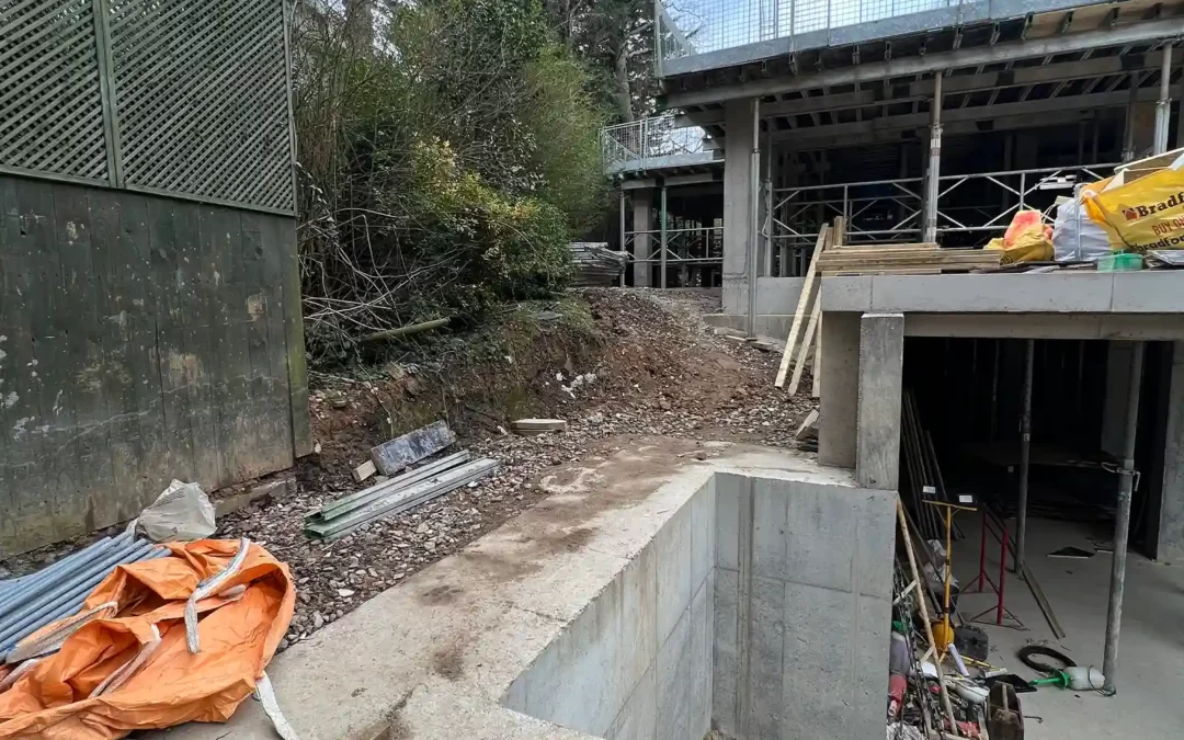
Retaining Walls
Retaining concrete walls play a crucial role in providing structural support and preventing soil erosion in areas with significant differences in ground elevations. These walls are designed to resist the lateral pressure exerted by soil and retain it in place. In landscaping projects, retaining concrete walls are often used to create terraces or multi-level platforms on sloped landscapes. By constructing these walls, different areas of the landscape can be transformed into usable spaces while preventing soil erosion and maintaining the stability of the terrain.
What Exactly is Concrete Design?
Concrete design requires a precise and accurate specification for structures built using reinforced concrete (RC) combined with steel reinforcement bars (often referred to as “rebar”). The THREE fundamental design tools used by reinforced concrete design services involve calculating:
- Working Stress Method (WSM)
Calculations are based on service load conditions only. WSM is used for reinforced concrete, structural steel, and timber. Structural design calculations involve limiting material stresses to expected “working loads.
- Ultimate Load Method (ULM)
Based on ultimate load conditions only. ULM analyzes stress conditions at the site of potential structural failure. Safety measures are designed with an acceptable load factor, defined as a ratio of “ultimate load” to “working load”.
- Limit State Method (LSM)
Based on safety at ultimate loads and serviceability at working loads. LSM investigates a state of imminent structural failure, considering characteristics such as strength, overturning, sliding, buckling, fatigue fracture, excessive deflection, cracking, vibration, leakage, and loss of durability.
Quality Control
Precision and quality control are essential throughout the concrete design process. Structural engineers’ calculations must comply with key building regulation standards, including support load and strength, fire resistance, durability, sustainability, surrounding atmosphere and climate, adverse/aggressive ground conditions, and contents of ground water.
Properties of Reinforced Concrete
Typical concrete design services for clients include structural calculations for reinforced concrete elements and performance values of its known properties. The key properties of concrete are:
Strength
One of the key design factors in calculating the strength quality of concrete is its water-to-cement ratio. A lower water content will provide stronger concrete. Concrete strength refers to the force or amount of load a specific element will safely support before cracking or leading to further structural failure.
Different Types of Foundations
Load pressure is rated by megapascals (MPa), equivalent to pounds per square inch (psi) or kilograms per square centimeter (kg/m2). Structural engineers will also calculate load pressure by the compressive strength and tensile strength of reinforced concrete.
Compressive strength is defined as the capacity of a material or structure to withstand loads and resist reducing in size. Typical concrete strengths range from low strength: 5 MPa to high strength: 80 MPa.
Tensile strength is defined as the maximum stress a material can withstand when stretched or pulled before breaking apart. This is referred to as its shear load capacity when material failure occurs along a plane parallel to the direction of the force applied.
Raft or Mat
The tensile strength of unreinforced concrete (low strength) is around 10 per cent lower than its compressive strength. Typical concrete tensile strengths vary between 2 MPa and 5 MPa.
Concrete Design to British Standards
A structural engineer’s steel specification throughout all concrete design
processes should clearly indicate the steel type, grade, and size. All drawings, testing calculations, and dimensions should be prepared in accordance with various British Standards.
Resilience
Concrete design also takes into account the material’s capacity for resilience – resistance to exterior and environmental forces including fire resistance, heat reflection, passive cooling, moisture prevention, durability, and sustainability.
Concrete Design Structural Elements
Structural engineers can specify a range of structural elements for reinforced concrete construction. Concrete ground beams are often specified for residential properties and a wide range of ground conditions. A key advantage of using ground beams is the same level of load-bearing strength, quick and accurate installation, and reliability.
Full concrete design services will include structural calculations for the following services:
Ground beams
Concrete ground beams are often specified by structural engineers for residential properties and a wide range of ground conditions. Particularly, where it’s not possible or unsuitable to install foundations.
A key advantage of using ground beams is:
- Same level of load-bearing strength.
- Installed quickly and accurately.
- Reliable.
- Long-lasting.
However, concrete ground beams will need reinforcement to create ‘tensile’ strength for withstanding a shear force. Ground beam reinforcement is usually in the form of traditional steel bars, known as ”rebar”, or mesh panels.
Structural engineers can also design concrete ground beams to support brick or blockwork. Additionally, beams can be used to form a permanent – instead of a temporary “shutter”, i.e. support mould – for fresh concrete, to the edge of a concrete floor slab.
Columns
Columns are designed to transfer loads from beams and slabs to foundation.
Structural engineers will design a concrete column, reinforced with an embedded steel frame to carry “compressive” loads, i.e. prone to reduce size of materials or structures.
Columns are classified according to different factors, including:
Reinforcement
Tied column – nearly all ‘reinforced’ columns are ‘tied’ where vertical reinforcement is closely and tightly spaced.
Spiral column – vertical bars are closely and tightly spaced within a continuously wound spiral.
Composite column – structural steel section, with or without vertical bars, offers high strength and fire resistance.
Loading
Axial – where vertical loads act upon the centre of gravity of a column.
Uniaxial Eccentric – where vertical loads do not act upon the centre of gravity of a column but, instead, act upon either on the X or Y axis. Usually installed where a beam is rigidly connected from one side of column only.
Biaxial Eccentric – where vertical loads do not act upon the centre of gravity of a column nor either on the X or Y axis. Usually installed where a beam is rigidly connected at right angles at the top of a corner column.
Slenderness Ratio, i.e. length vs least width
Short column – where the ratio of the column length versus the least column width is less than 12. A ‘short’ column failure is caused by ‘compression’.
Long column – where the ratio of the column length versus the least column width is more than 12. A ‘long’ column failure is caused by ‘bending’ or ‘buckling’.
Shape
Square or Rectangular – an easier type of support mould ‘shuttering’ while concrete is being introduced than using circular columns.
Circular – bespoke design by structural engineers for intended use in ‘piling’ and structural elevation.
L-Shape – similar properties to a square or rectangular column, mostly specified for the corners of a boundary wall.
T-Shape – a column design most often used in the construction of bridges.
Construction Material
The specified material to be used to create structural columns includes:
Reinforced Concrete
Steel
Timber
Block
Stone
Raft foundations
Raft foundations are reinforced concrete slabs which ‘float’ on the ground underneath an entire structure or property extension.
At the same time, raft foundations spread the structural load across a much wider concrete surface area than other types of foundations.
Installing raft foundations is usually specified and designed to handle wide variations in land types. Thereby, reducing potential load bearing pressure on the ground surface.
However, a structural engineer will be essential for designing raft foundations, because:
A detailed site investigation is usually needed to carefully assess ground conditions.
Raft foundation are usually considered only suitable for a specific type of building project.
Design concept normally requires an ‘edge beam’ formed by steel cage reinforcement, and carefully built on-site.
Internal reinforcing beams are sometimes also needed to evenly transfer building loads across the ground slab area.
Floor slabs
There are generally two main types of concrete slabs which structural engineers might specify for the ground floor of a building or similar structure:
Suspended slab – supported on beams.
Ground-bearing slab – supported directly on the subsoil.
A ‘slab’ usually refers to a floor made with steel-reinforced concrete. But not a floor made of timber or other structural materials. Slabs may also form part of a building structure, such as the floor of a basement or at upper levels.
Floor slabs usually refers to a finished material product such as:
Flat, horizontal concrete planes – minimum 10cm (4 in) in depth –(i) Supported on two or more sides by concrete or steel beams.-or-(ii)
Supported by profiled, steel-ribbed sheet decking.
Flat, horizontal concrete poured over a beam and block substructure or a hollow-rib structure and rebar.
‘Waffle’ slab – formed on slab underside by concrete poured over a series of ‘egg-crate’ plastic formers.
Piles
Pile beams – or ‘piles’- refer to long slender concrete columns used for installing deep foundations, when their depth is more than three times their width.
Structural engineers typically design pile beams for very large structures, and for sites where the ground soil is not suitable because of unstable conditions, such as excessive settlement.
Piles are designed to transfer loads down through unstable ground onto stronger, soil or rock at lower levels. They are usually installed with ground beams, and approximately at ground level. The size of a foundation is, therefore, increased to resist horizontal loads, and tend to run vertically alongside the perimeter of a planned building or structure.
The varying types of piles that may be specified include:
Driven piles or “displacement” piles
Piles are installed into the ground, by
displacing instead of removing the material outwards and downwards from the pile shaft.
Bored piles or “replacement” piles
Ground soil and rock is removed to form a hole for the pile to be poured in. Minimal vibration means this method is commonly used in urban areas for installing pile foundations close to existing buildings.
Micropiles or “mini” piles
Engineers will use mini piles, which have a relatively small diameter, and where site access is restricted. The size of the pile will be calculated by the ground’s load-bearing capacity, and size of machinery capable of accessing site location.
Minipiles are particularly suitable for property locations where underpinning is required, e.g. foundations adjacent to planned excavations.
Pile caps
Pile caps function in a similar way to piled raft foundations, where a concrete slab rests on ground soil prone to movement.
When piles are installed in a group they are joined together by a reinforced concrete cap. Use of pile caps secures a stable foundation across a larger area for distributing structural load on to pile beams.
Retaining Walls
Structural engineers design and specify retaining walls for:
Holding back material to one side of an incline or slope.
Preventing a collapse, slippage or erosion.
Retaining walls are basically grouped as :
‘Cut’ walls – retaining wall is cut into an existing slope.
‘Fill’ walls – retaining wall is built in front of the slope, and space behind is filled.
Engineers can select from a wide range of retaining walls, often including:
Gravity retaining walls
A wall which relies on its mass acting as a firm and stable resistance against material it holds back. The most common materials used to build this type of wall are stone, concrete and brick masonry.
Wall stability will be maintained if the mass and friction of the wall materials are greater than the force of the materials being held back.
Engineers can increase the resistance pressure by designing gravity retaining walls to have a ‘battered’ profile, either on the face or back of the wall.
A battered profile is – an inclined or sloping face where the wall is wider at the base than at the top, i.e. wall base should be half to three-quarters of wall height.
Gravity retaining walls are generally most effective when built to heights of between 2 – 3 metres.
Concrete pile walls
Structural engineers will design concrete pile walls to create permanent or temporary retaining walls.
This type of wall is built by placing piles directly side-by-side, either:
Closely-spaced or in actual contact with each other.
-or-
Interlocking or meeting at a curve.Reinforced retaining wall
Reinforcement bars can be specified to assist in providing additional stability to reinforced concrete and masonry walls.
An outward, horizontal pressure from behind the retaining wall can be directed downwards to the ground as a vertical pressure.
A long, projecting beam or girder attached one end – known as a cantilever – made of steel-reinforced concrete can be connected to a slab foundation in the shape of an inverted ‘T’ or ‘L’.
Where the height of a retaining wall is greater than 8-12 metres, angled support beams – known as counterfort buttresses – are attached at equal distances along the inside face of the wall. The buttresses will resist further lateral thrust and create a structural path between a vertical wall and a horizontal base.
It is important to note that permission is required if a retaining wall is designed to be:
Over 1-metre high when built next to a road or pathway.
-or-
Over 2-metres high for all other locations.
Performance and Sustainability
A concrete design team and its engineers constantly work to improve performance. An increasingly vital role in creating a sustainable, built environment.
The application of quality concrete design and precise engineering calculations to any building project is essential to future sustainability.
Whole-life carbon
Creating low energy structures is a central concern of contemporary building design. The growing need for sustainability focuses upon key issues such as ‘whole-life carbon’.
Whole-life carbon refers to total carbon emissions from :
Materials used.
Construction process.
Use of building over entire lifecycle, including demolition and material disposal.
Building structure contributes about 25 per cent of carbon emissions. (Source: “Building to net zero: costing carbon in construction” – Environmental Audit Committee | EAC, June 2022).
However, concrete construction is shown to be responsible for around 6 per cent of whole-life carbon emissions over a 60 year building life.
A design for concrete low-rise housing is found to have even less whole-life carbon emissions – around 1 – 4 per cent over a 60 year life cycle compared to timber construction.
Thermal mass
Thermal mass is defined in structural engineering as, “how the mass of a building provides inertia, i.e. material resistance to change – against fluctuations of internal temperature.”
The concrete design process can calculate even comparatively small differences in “embodied carbon”, i.e. all the carbon emitted in producing materials.
Climate heating now plays an increasingly role for structural concrete design in reducing a building’s cooling demand . The introduction of thermal mass into the design process can help lower “peak” space-heating and cooling loads.
Air tightness
Air tightness refers to how uncontrolled air leakage in buildings is measured and controlled. A limit is set for the maximum acceptable level of air leakage in new buildings by Part L1A and L2A of the Building Regulations, 2006.
Fire resistance
Concrete is highly fire-resistant, and does not emit toxic fumes when impacted by fire.
The main properties of concrete – cement and aggregates – are chemically combined to form an “inert” material. Its mass has slow heat transfer – or ‘thermal conductivity’.
The essential properties of concrete combined with correctly calculated and specified structural elements are key to “fire performance” and structural integrity.
Fire performance is defined as the ability of a specific structural element to function for a set period of time according to its designed structural purpose.
Flood resilience
Concrete is naturally water-resilient. The level of water prevention depends on:
Material specification and specific design details.
The high water resilience of on-site and precast concrete produces minimal building damage or structural pressures and distortion under flood conditions.
Water resistance and common concrete design structures
Concrete floor slabs (min. 100mm, ground supported) – prevents loss of structural integrity resulting from uplift pressure caused by water entry from the ground.
Concrete Walls ( solid masonry or clear cavity ) – can give higher flood resilience than filled or part-filled cavity walls.
Acoustic performance
The natural ‘mass’ and noise proofing properties of concrete provide highly efficient sound insulation for walls and floors. Only minimal sound-dampening or an acoustic finish may be added for a specific requirement.
Engineers would design a concrete wall to be around 300 mm (12 inches) thick to be completely soundproof. This compares favourably against a standard ‘stud’ wall, consisting of 2 sheets of drywall to create an internal air cavity, measuring half the width at 125 – 150 mm (5 to 6 inches) to be soundproof.
Code for sustainable homes
Improving the sustainable construction of “legacy developments” continues to receive a government boost from its Code for Sustainable Homes (CFSH), 2006.
The design and use of concrete as a sustainable and highly energy-efficient building material was repeatedly demonstrated by properties achieving the highest CFSH ratings.
An equally high number of concrete building elements also attained the highest A and A+ ratings in the Green Guide for housing, such as blockwork cavity walls.
Further high performance ratings for concrete extended to:
Responsible materials sourcing
Flood resilience
Sound insulation

Zaeem Chaudhary
Zaeem is a co-founder who leads the Architecture and Structural team with tricky complexed projects, whether these involved multi storey high rise building or small extension, he has a strong track of obtaining grant of approval and finding solution to complexed structural issues.
Write us a message
We look forward to learning how we can help you. Simply fill in the form below and someone on our team will get back to you within two business days.
Read other posts
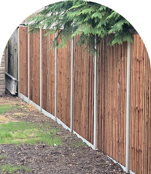
Understanding Party Fence Walls and Boundary Walls
Summary not available. Please add an excerpt manually.
The History of Building Regulations and Building Control
Building regulation has grown over centuries. It started with basic fire safety. Now it covers complete systems for construction standards, safety, and the environment. The history of building regulations in British history shows how building control moved from old guild systems to modern national standards.
DIY Loft Conversion: A Complete Guide to Convert Your Loft
Summary not available. Please add an excerpt manually.
Party Wall Act 3 Metre Rule: Complete Guide
SumThe Party Wall Act 3-metre rule requires formal notice when excavating within 3 metres of a neighbouring building’s foundation if digging deeper than those foundations. This protects structural stability during construction work near boundaries.mary not available. Please add an excerpt manually.
Building Regulations Part A Structure: Complete Guide to Approved Document A 2025
Building Regulations Part A Structure governs structural integrity under the Building Regulations 2010 framework. Approved Document A 2025 provides guidance on structural loading, foundations, and calculations for safe construction work.

How Much Does a Party Wall Surveyor Cost? – Complete Guide 2025
Party wall surveyor costs range £90-£450/hour with average projects around £1,050-£1,500. Building owners pay all fees including neighbour’s surveyor. Costs double with separate surveyors or triple if third needed. London rates £1,000-£2,000. Key tip: agree on single surveyor.
How Long Does a Loft Conversion Take
Converting your loft into a functional living space is one of the most effective ways to add value to your property without the hassle of moving. Whether you’re considering a simple Velux conversion or a more complex dormer extension
Which Type of Loft Conversion is Right for Your Home?
Choosing the right loft conversion type depends on your property’s roof structure, planning constraints, and space requirements. From simple Velux conversions to complex mansard extensions, explore all options to find the perfect solution for your home and budget needs.
A Guide To Domestic Stairs: UK Building Regulations Part K
Complete guide to UK domestic staircase regulations under Building Regulations Part K. Covers rise and going requirements, pitch regulations, handrail specifications, and safety compliance for all types of domestic stairs including loft conversions and space-saver staircases.

5 Things to Know Before Doing a Hip to Gable Loft Conversion
A hip-to-gable conversion removes the sloped hip end of your roof and replaces it with a vertical gable wall, creating significantly more usable loft space and headroom than other conversion types but usually requiring planning permission.
Ready to unlock the potential of your project?
We speciallise in crafting creative design and planning strategies to unlock the hidden potential of developments, secure planning permission and deliver imaginative projects on tricky sites