Steel beams and columns may form the main structural frame, but they can only work as intended if the connections between them are properly designed.
A steel connection has to transfer the forces assumed in the structural analysis while also being practical to fabricate, transport and install.
That makes steel connection design much more than deciding how many bolts should pass through a plate.
The designer needs to understand the forces being transferred, how the joint is expected to behave, the geometry of the members, the available space for bolts and welds, fabrication tolerances and how the steelwork will actually be assembled on site.
This becomes particularly important in extensions and structural alterations, where new steelwork needs to fit around an existing building rather than an empty structural grid.
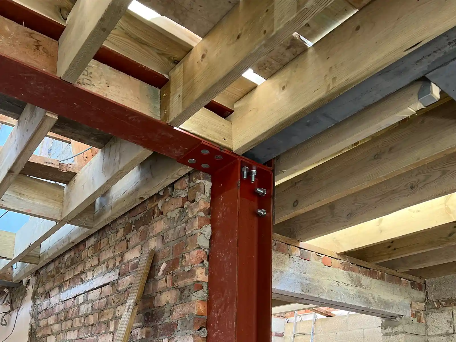
At 16 Vivian Road, Bow, for example, AC Design Solution’s structural design for a large open-plan lower-ground floor required two bespoke cranked steel frames. The package included UC beams and columns, bespoke end plates, stiffeners, bolted connections and full-penetration welded joints. Because the frames were being inserted into an existing terraced property, their cranked dimensions also had to be checked against actual site levels before fabrication.
That is a useful example of what connection design actually involves: making the structural analysis, architectural geometry, fabrication and real building work together.
For projects involving structural alterations, AC Design Solution provides dedicated structural calculations and drawings alongside its wider structural engineering work. The service specifically covers beams, foundations, structural changes and connection details for Building Control submissions.
What Is Steel Connection Design?
A steel connection is the interface through which structural forces pass from one member to another.
Typical examples include a beam connecting to a column, a secondary beam connecting to a primary beam, two beam sections being spliced together, a column splice or a steel column connecting to its supporting foundation.
Depending on the structural arrangement, a connection may need to transmit:
- shear force;
- axial tension or compression;
- bending moment;
- or a combination of these actions.
The connection therefore needs to be compatible with the behaviour assumed in the engineer’s structural model.
This distinction is important.
A connection should not simply be called “simple” or “moment-resisting” because of how it looks. Its resistance, stiffness and rotational behaviour need to suit the assumptions made when the structure was analysed.
UK steel construction guidance distinguishes nominally pinned connections from moment-resisting connections and sets out the conditions under which commonly used simple joints can be treated as nominally pinned.
SteelConstruction.info guidance on simple connections
Which Standard Applies to Steel Connection Design in the UK in 2026?
Steel connection design is currently going through an important Eurocode transition.
BS EN 1993-1-8:2024 — Eurocode 3: Design of steel structures – Joints is the published second-generation Eurocode 3 standard covering structural joints.
However, this does not mean designers should automatically replace the first-generation UK Eurocodes on every current project.
BSI explains that the first-generation Eurocodes and their UK National Annexes should generally continue to be regarded as the applicable standards for UK buildings and civil engineering works until 30 March 2028, unless a relevant authority or individual project specification states otherwise. BSI also warns that provisions from the two generations should not be mixed casually.
BSI information on the UK Eurocode 3 transition
The second-generation UK National Annex specifically for BS EN 1993-1-8:2024 is also still within BSI’s standards-development programme as of September 2026.
BSI development of the new UK National Annex for Eurocode 3 Part 1-8
For that reason, the correct design basis should be established for the particular project rather than simply changing the standard reference because a newer document has been published.
This is also why the previous “UK 2023” version of this guide needed a proper technical refresh rather than simply changing the year in the title.
Main Types of Steel Connections
There are many forms of steel connection, but most building projects will encounter several recurring categories.
| Connection | Typical purpose |
|---|---|
| Nominally pinned / simple connection | Transfers the required forces while allowing the rotation assumed in simple construction |
| Moment-resisting connection | Transfers significant bending moment and provides rotational continuity |
| Beam splice | Joins two lengths of beam |
| Column splice | Transfers forces between sections of a column |
| Column base | Connects a steel column to the supporting foundation |
| Bracing connection | Transfers forces from stability bracing into the main structural frame |
The visual appearance of a connection is not enough to classify it.
The engineer or connection designer needs to confirm that its structural behaviour is consistent with the analysis.
Simple and Nominally Pinned Connections
Simple connections are widely used in braced steel structures.
They are generally modelled as nominally pinned, meaning that they are intended to transfer the required actions while allowing sufficient rotation for the assumptions used in simple construction.
Common UK forms include:
fin plates, partial-depth end plates and full-depth end plates.
SteelConstruction.info identifies these as common simple beam-to-beam and beam-to-column connections and explains the conditions under which they can be classified as nominally pinned.
Technical guidance on nominally pinned steel connections
This is more accurate than the wording in the old article, which broadly described shear connections as “semi-rigid”.
The structural behaviour should come from the actual joint design, not from a generic label.
What Is a Fin Plate Connection?
A fin plate connection is one of the most commonly recognised forms of simple steel connection.
A plate is typically welded to the supporting member during fabrication. The supported beam is then positioned on site and bolted through its web to that plate.
This arrangement can be used for beam-to-column or beam-to-beam connections.
Its relatively simple appearance does not mean that no engineering is involved.
The designer may still need to consider the bolts, plate, weld, supported beam, supporting member and the way the applied forces pass through the joint.
The eccentric relationship between the beam reaction and supporting face also means that the fin plate does not behave as though it is carrying only a perfectly centred vertical force.
For project-specific design, AC Design Solution’s structural drawings and calculations service includes connection details as part of the wider structural package where required.
Moment-Resisting Connections
A moment-resisting connection is used where the structural system intentionally relies on the joint to transfer significant bending moments.
Common arrangements can include bolted end-plate beam-to-column connections, beam splices and welded connections.
In these structures, rotational continuity between the members contributes directly to the behaviour of the frame.
Connection stiffness and resistance therefore need to reflect the assumptions used in the structural analysis.
SteelConstruction.info identifies full-depth and extended end plates among common moment-resisting solutions and explains why stiffness becomes particularly important in continuous and unbraced frames.
SteelConstruction.info guidance on moment-resisting connections
A moment connection should therefore not be chosen simply because it appears “stronger”.
It needs to form part of a deliberate structural system.
Bolted vs Welded Steel Connections
Both bolted steel connections and welded steel connections are widely used in UK construction.
A bolted connection can make site erection more practical because components can be prepared in the fabrication workshop and then assembled on site.
Welded connections can produce efficient and compact joints, but the weld type, execution, access and inspection requirements all depend on the particular detail.
Many real connections use both approaches.
For example, a steel plate may be welded to one member in the workshop and then bolted to another member during erection.
The better question is therefore not:
“Are bolts or welds better?”
It is:
“Which arrangement transfers the required forces while remaining practical to fabricate and erect?”
Fabrication and erection also have their own technical requirements. The current BS EN 1090-2:2018+A1:2024 standard covers execution of structural steelwork, including fabrication, welding, geometrical tolerances, inspection and testing.
BSI – BS EN 1090-2:2018+A1:2024
What Does a Steel Connection Designer Check?
A connection should be treated as a collection of interacting components rather than simply a bolt or weld.
Depending on the detail and forces involved, structural checks can include:
- bolt shear and tension;
- plate bearing;
- weld resistance;
- plate bending;
- beam or column web resistance;
- flange behaviour;
- stiffeners;
- connection stiffness;
- tying and robustness requirements;
- and combinations of shear, axial force and bending moment.
The exact checks depend on the connection.
There is no single calculation template that applies to every steel joint.
This is why structural calculations should be prepared from the actual building arrangement rather than selecting an RSJ or connection from a generic online table.
AC Design Solution’s house structural engineer service covers structural assessment and design for domestic works where beams, openings and supporting elements need to be considered together.
Real Project: Bespoke Steel Connections at 16 Vivian Road, Bow
The work at 16 Vivian Road, Bow gives a useful example of steel connection design within an existing residential building.
The project involves a lower-ground-floor wraparound extension, first-floor rear addition and mansard roof.
At lower-ground level, the architectural brief called for a continuous open-plan kitchen, dining and family space without introducing new internal masonry walls.
A single standard beam was not enough to resolve the geometry.
AC Design Solution’s structural design therefore incorporated two bespoke cranked steel box frames.
One frame uses UC254×254×73 beams with UC203×203×46 columns. The heavier frame uses UC254×254×107 beams with UC203×203×60 columns.
The upper members were cranked to follow the slopes of the proposed extension roofs.
This allowed the primary structure to work with the architectural roof form rather than introducing a deep straight beam underneath the proposed ceiling.
The steelwork package included bespoke end plates, stiffeners, bolted connections and full-penetration welded joints.
Because the steelwork was being inserted into an existing terraced house, the cranked dimensions were also specified to be verified against the actual site levels before fabrication.
That last point is particularly important.
A steel connection can be calculated correctly but still cause serious construction problems if the fabricated geometry does not match the existing building.
Steel connection design in refurbishment work therefore needs to consider site measurement and buildability as well as resistance calculations.
Another Project Example: Minet Gardens
A different example appears at AC Design Solution’s Minet Gardens extension and loft conversion project.
The loft conversion involved removing the existing hip roof and chimney and opening up the property to create the enlarged loft space.
That work required structural calculations covering load paths, beam sizing, connection details and the structural design of the new roof. The engineering package was coordinated with the Building Regulation drawings from the outset.
This demonstrates another important point: connection detailing does not sit separately from the wider structural design.
The load path, beam size, bearing arrangement and connection all need to work together.
Steel Connections and Structural Load Paths
Every connection forms part of a structural load path.
Loads from floors, roofs and walls pass into beams or other supporting elements, through their connections and eventually down into the foundations.
The steel connection therefore needs to be designed for the forces generated by the entire structural system rather than selected independently afterwards.
This is particularly important when a homeowner wants to create a large opening by removing structural walls.
Removing a load-bearing wall may require more than a steel beam.
The engineer also needs to establish how the beam is supported, what reactions occur at its ends, whether columns or padstones are needed, how the supporting structure carries those reactions and whether a steel frame is required instead of a single simply supported member.
For further project-specific guidance, AC Design Solution’s load-bearing wall removal service covers the wider engineering involved when existing walls are removed.
Why Existing Buildings Need Extra Verification
Connection design becomes more difficult when the building already exists.
Original structural drawings may be incomplete or unavailable.
Existing beams may not be exactly where expected.
Walls may have been altered previously.
Floor levels may vary.
A previous renovation may also have changed the original load paths.
Before finalising steelwork, it can therefore be necessary to verify the existing structure through surveys, measurements or targeted opening-up.
AC Design Solution’s Structural Survey London service explains how existing structural conditions and visible defects can be assessed before major alterations proceed.
This should not be confused with routine connection calculations.
The purpose of the survey is to establish reliable information about the existing structure so that the subsequent design is based on what is actually there.
Steel Connection Design and Building Regulations
Structural work in England also needs to satisfy the relevant requirements of the Building Regulations.
Approved Document A provides statutory guidance relating to structural safety, including loading and the construction of foundations, walls, floors and roofs.
GOV.UK – Approved Document A: Structure
Steel connection calculations are only one part of the wider technical submission.
Depending on the project, Building Regulations information can also need to address fire safety, insulation, ventilation, drainage and the relationship between structural elements and the rest of the construction.
AC Design Solution’s Building Regulation drawings service coordinates structural information with the wider technical package rather than treating beams and connections as isolated details.
This coordination matters particularly where a beam or connection needs to fit inside insulation, ceilings, fire protection or architectural finishes.
Steel Connections and Structural Robustness
A connection is not only responsible for transferring the obvious reaction from one beam to another.
Depending on the building and structural system, connections can also form part of the measures used to provide overall structural integrity and robustness.
Approved Document A includes guidance relating to structural stability and disproportionate collapse, while UK steel construction guidance explains that simple beam-to-column connections and column splices may also need to resist specified tying forces.
This is another reason connection design should not be reduced to a single shear-force check.
The wider structural role of the connection needs to be understood.
Who Is Responsible for Steel Connection Design?
There is no single contractual arrangement that applies to every project.
On larger structural-steel projects in the UK, it is common for the main structural engineer to establish the structural arrangement, member forces and required joint behaviour, while the detailed connection design is developed by the steelwork contractor.
Steel Construction Institute guidance describes this as a common UK arrangement and emphasises the importance of the structural engineer’s assumptions being realistic enough to be turned into practical connections.
SCI guidance on structural design and connection responsibility
Domestic structural alterations can follow a different arrangement.
For projects such as extensions, loft conversions and load-bearing wall removals, the structural engineer’s own package may contain considerably more detailed connection information.
The important point is that responsibility must be clear.
There should not be a gap where the structural analysis assumes one type of connection but nobody has responsibility for designing or detailing it.
Why Buildability Matters in Connection Design
A structurally adequate connection that cannot sensibly be manufactured or installed is not a successful design.
Connection detailing should therefore consider the physical realities of construction.
Bolt access
There needs to be enough room to install and tighten the bolts.
Weld access
The specified weld needs to be achievable in the intended fabrication or site environment.
Member clashes
Where several beams meet around the same column, connection plates, bolt heads and stiffeners need physical space.
Erection sequence
The steelwork has to remain safe while individual members are being placed and connected.
Tolerances
The real building may not exactly match the design model, especially during refurbishment work.
Fire protection and finishes
Connections may need to fit inside fire protection, ceiling zones, walls or architectural finishes.
BS EN 1090-2 provides the wider execution framework for matters including fabrication tolerances, welding, inspection and testing.
At Vivian Road, the requirement to check the cranked frame dimensions against actual site levels before fabrication is a good example of this relationship between engineering and buildability.
Are Hollow-Section Connections Different?
They can be.
Square, rectangular and circular hollow sections are widely used in structural steelwork, but connections into hollow sections can require different detailing from conventional I- or H-section connections.
The joint may need to consider local wall behaviour, weld geometry, member dimensions and how forces enter the hollow section.
Eurocode 3 Part 1-8 contains provisions relating to steel joints, including hollow-section joints within its scope. The current published second-generation standard is BS EN 1993-1-8:2024, subject to the UK transition arrangements discussed earlier.
BS EN 1993-1-8:2024 – Eurocode 3 Joints
The connection should therefore be designed around the specific hollow section and loading rather than assuming that a detail suitable for an open UC or UB section can simply be transferred across.
What About Column Base Connections?
A column base transfers loads from the steel column into the supporting concrete or foundation.
The detail can involve a base plate, holding-down bolts or anchors, grout and the concrete foundation beneath.
Depending on the structure, the base may need to transfer axial compression, horizontal shear, uplift and bending moment.
Its behaviour also depends on the stiffness of the supporting foundation and ground below.
Column base design therefore demonstrates an important principle of connection engineering:
the connection cannot be understood independently of what it is connected to.
A heavily reinforced steel base plate is not useful if the supporting foundation cannot safely resist the forces transferred into it.
Steel Connection Design Software and BIM
Software is an important engineering tool, but it does not automatically design a good connection.
Connection-analysis software can help engineers calculate component resistances, evaluate bolt groups, welds, plates and joint behaviour and compare different arrangements efficiently.
Three-dimensional structural modelling and BIM can also help identify clashes before steel is fabricated.
But software still relies on engineering decisions.
The designer needs to determine:
- which forces the connection must resist;
- what joint behaviour is assumed;
- which combinations of loads govern;
- whether the geometry represents the real building;
- whether the detail can actually be fabricated;
- and whether the proposed connection fits the architectural construction.
The calculation output is therefore only part of the design process.
Engineering judgement remains essential.
The wider value of coordinated technical information can also be seen in AC Design Solution’s Building Regulation drawings service, where structural, architectural and MEP information is coordinated to identify conflicts before construction.
What Information Is Needed Before Designing a Steel Connection?
For a new building, connection design may be based on coordinated structural drawings, analysis models, design actions and member schedules.
For an existing building, more investigation can be required.
Useful information can include the member sizes, support locations, actual site dimensions, floor levels, existing material and construction, proposed structural loads and how new steelwork interfaces with the old structure.
In some cases, targeted opening-up may be needed to confirm what is hidden behind finishes.
This is particularly important before fabrication.
Changes of a few millimetres can sometimes be accommodated.
A fundamentally incorrect assumption about an existing wall, floor level or beam position can require the steelwork to be redesigned or remade.
When Do You Need a Structural Engineer for Steelwork?
If proposed building work alters a load-bearing part of a property, professional structural input is commonly required.
Examples include large openings, removal of load-bearing walls, extensions, loft conversions, new structural frames and changes that alter the load path through the building.
The structural engineer needs to determine not only the member sizes but also how those members are supported and connected.
AC Design Solution’s structural engineering service for houses and extensions covers this wider assessment, while the structural calculations and drawings service provides the detailed technical information required for Building Control and construction.
Steel Connection Design: The Key Principle
There is no universally “best” steel connection.
A good connection is one that transfers the required forces, matches the assumptions in the structural analysis and can be fabricated and installed reliably in the actual building.
For one project, that may be a straightforward fin plate.
For another, it may be a moment-resisting end plate.
For a constrained residential alteration such as Vivian Road, it can mean bespoke end plates, stiffeners, bolts and welded joints coordinated around cranked steel frames and existing site geometry.
The important point is that the connection should not be treated as an afterthought.
Member sizing, joint behaviour, fabrication, site conditions and construction detailing all need to work as one structural system.
Frequently Asked Questions
What is steel connection design?
Steel connection design determines how structural members such as beams and columns are joined so that the forces acting on the structure can safely pass between them. Connections can incorporate bolts, welds, plates, stiffeners and other components depending on the structural arrangement.
What is the difference between a simple and moment connection?
A nominally pinned or simple connection is designed to provide the rotational behaviour assumed in simple construction while transferring the required actions. A moment-resisting connection intentionally transfers significant bending moments and provides greater rotational continuity within the frame.
What is a fin plate connection?
A fin plate typically consists of a steel plate welded to a supporting beam or column and bolted through the web of the supported beam. It is commonly used as a nominally pinned connection in UK steel construction.
Are steel connections bolted or welded?
They can be bolted, welded or a combination of both. A common arrangement is for components to be welded in the fabrication workshop and then bolted together during erection.
Which Eurocode covers steel connection design?
Eurocode 3 Part 1-8 covers the design of steel joints. BS EN 1993-1-8:2024 is the published second-generation version, but BSI states that first-generation Eurocodes should generally remain the applicable standards for UK construction until 30 March 2028 unless otherwise specified.
What standard covers steel fabrication and execution?
BS EN 1090-2:2018+A1:2024 provides current requirements for execution of structural steelwork, including fabrication, welding, tolerances, inspection and testing.
Does a structural engineer design every steel connection?
Not necessarily. On larger UK steel-framed projects, detailed connection design is commonly undertaken by the steelwork contractor using the forces and connection requirements supplied by the structural designer. On smaller or bespoke structural projects, the structural engineer’s package may include detailed connection design. Responsibilities should be clearly established.
Do steel connections require calculations?
Where structural adequacy needs to be demonstrated, the resistance and behaviour of the relevant connection components need to be verified. The exact calculations depend on the connection, loads and structural system.
Can steelwork be ordered before the existing building is measured?
That can create unnecessary risk on refurbishment projects. Where fabricated steel dimensions depend on existing walls, supports or levels, those conditions should be verified before final fabrication information is issued.
Do Building Regulations apply to structural steelwork?
Structural alterations and structural elements need to satisfy the applicable Building Regulations requirements. In England, Approved Document A provides statutory guidance on structural safety.
Need Steel Connection Design or Structural Calculations?
Steel connection design should form part of the wider structural solution rather than being added after all the beam sizes and architectural details have already been fixed.
AC Design Solution provides structural calculations and drawings for residential and commercial projects, alongside Building Regulation drawings where a coordinated technical package is required.
The Vivian Road project demonstrates this approach in practice, with the architectural geometry, cranked steel frames, bespoke connection details and actual site dimensions coordinated within the same technical design process.
For existing buildings where the structural arrangement needs to be established first, a structural survey may also be relevant before the final steel design is completed.
For project-specific advice, contact AC Design Solution.